|
|
|
|
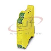
Image is illustrative
|
Coupling Relay PSR-SCP- 24DC/FSP2/2X1/1X2, Phoenix Code:
2986575
Cena (indicative)
Manufacturer
:
|
Availability:
21 days
|
Weight:
0.1155 kg/pc
|
Volume:
0.0002 m3/pc
|
|
|
|
|
Coupling Relay PSR-SCP- 24DC/FSP2/2X1/1X2, PhoenixNote
|
Utilization restriction
|
EMC: class A product, see manufacturer's declaration in the download area
|
Dimensions
|
Width
|
17.5 mm
|
|
Height
|
99 mm
|
|
Depth
|
114.5 mm
|
Ambient conditions
|
Ambient temperature (operation)
|
-20 °C ... 55 °C (observe derating)
|
|
Ambient temperature (storage/transport)
|
-40 °C ... 70 °C
|
|
Max. permissible relative humidity (operation)
|
75 % (on average, 85% infrequently, non-condensing)
|
|
Max. permissible humidity (storage/transport)
|
75 % (on average, 85% infrequently, non-condensing)
|
|
Maximum altitude
|
≤ 2000 m (Above sea level)
|
Input data
|
Rated control circuit supply voltage US
|
24 V DC -15 % / +10 %
|
|
Rated control supply current IS
|
typ. 55 mA
|
|
Input voltage range
|
20.4 V DC ... 26.4 V DC
|
|
Power consumption at US
|
typ. 1.32 W
|
|
Inrush current
|
max. 100 mA
|
|
Typ. starting time with Us
|
50 ms
|
|
Typical release time
|
50 ms
|
|
Recovery time
|
1 s
|
|
Operating voltage display
|
1 x yellow LED
|
|
Protective circuit
|
Surge protection Suppressor diode, 33 V (A1 - A2)
|
|
Maximum switching frequency
|
0.5 Hz
|
|
Filter time
|
max. 5 ms (at A1 in the event of voltage dips at Us)
|
|
|
max. 2 ms (Test pulse width; high test pulse at A1/A2)
|
|
|
≥ 100 ms (Test pulse width; high test pulse at A1/A2)
|
|
|
Test pulse rate = 80 x Test pulse width
|
|
|
max. 5 ms (Test pulse width; low test pulse at A1/A2)
|
|
|
≥ 50 ms (Test pulse rate; low test pulse at A1/A2)
|
|
|
Test pulse rate = 15 x Test pulse width
|
Output data
|
Contact type
|
2 enabling current paths
|
|
|
1 confirmation current path
|
|
Contact material
|
AgCuNi, + 0.2 µm Au
|
|
Maximum switching voltage
|
250 V AC/DC (N/O contact / N/C contact, observe the load curve)
|
|
Minimum switching voltage
|
15 V AC/DC (N/O contact / N/C contact)
|
|
Limiting continuous current
|
5 A (N/O contact, pay attention to the derating)
|
|
|
100 mA (N/C contact)
|
|
Maximum inrush current
|
5 A (N/O contact)
|
|
|
100 mA (N/C contact)
|
|
Inrush current, minimum
|
5 mA (N/O contact / N/C contact)
|
|
Sq. Total current
|
50 A2 (observe derating)
|
|
Interrupting rating (ohmic load) max.
|
120 W (24 V DC, τ = 0 ms, N/C contact: 2.4 W)
|
|
|
192 W (48 V DC, τ = 0 ms, N/C contact: 4.8 W)
|
|
|
162 W (60 V DC, τ = 0 ms, N/C contact: 6 W)
|
|
|
66 W (110 V DC, τ = 0 ms, N/C contact: 11 W)
|
|
|
60 W (220 V DC, τ = 0 ms, N/C contact: 22 W)
|
|
|
1250 VA (250 V AC, τ = 0 ms, N/C contact: 25 VA)
|
|
Maximum interrupting rating (inductive load)
|
72 W (24 V DC, τ = 40 ms, N/C contact: 2.4 W)
|
|
|
43 W (48 V DC, τ = 40 ms, N/C contact: 4.8 W)
|
|
|
41 W (60 V DC, τ = 40 ms, N/C contact: 6 W)
|
|
|
35 W (110 V DC, τ = 40 ms, N/C contact: 11 W)
|
|
|
48 W (220 V DC, τ = 40 ms, N/C contact: 22 W)
|
|
Switching capacity
|
min. 75 mW
|
|
Mechanical service life
|
10x 106 cycles
|
|
Output fuse
|
10 A gL/gG (N/O contact)
|
|
|
4 A gL/gG (for low-demand applications)
|
|
|
150 mA Fast-blow (N/C contact)
|
General
|
Relay type
|
Electromechanical relay with force-guided contacts in accordance with IEC/EN 61810-3
|
|
Nominal operating mode
|
100% operating factor
|
|
Net weight
|
136.3 g
|
|
Mounting position
|
any
|
|
Mounting type
|
DIN rail mounting
|
|
Degree of protection
|
IP20
|
|
Min. degree of protection of inst. location
|
IP54
|
|
Housing material
|
Polyamide
|
|
Housing color
|
yellow
|
Connection data
|
Connection method
|
Screw connection
|
|
pluggable
|
Yes
|
|
Conductor cross section solid
|
0.2 mm² ... 2.5 mm²
|
|
Conductor cross section flexible
|
0.2 mm² ... 2.5 mm²
|
|
Conductor cross-section AWG
|
24 ... 12
|
|
Stripping length
|
7 mm
|
|
Screw thread
|
M3
|
Safety-related characteristic data
|
Stop category in accordance with IEC 60204
|
0
|
|
Designation
|
IEC 61508 - High demand
|
|
Safety Integrity Level (SIL)
|
2 (max. 10% of the entire SIL; diagnostic coverage (DC) of the control unit at A1/A2 must be ≥ 90% )
|
|
Designation
|
IEC 61508 - Low demand
|
|
Safety Integrity Level (SIL)
|
2 (max. 10% of the entire SIL; diagnostic coverage (DC) of the control unit at A1/A2 must be ≥ 90% )
|
|
Designation
|
EN ISO 13849
|
|
Performance level (PL)
|
c (Diagnostic coverage (DC) of the control unit at A1/A2 must be ≥ 90 %)
|
|
Category
|
1 (Diagnostic coverage (DC) of the control unit at A1/A2 must be ≥ 90 %)
|
|
Designation
|
EN 62061
|
|
Safety Integrity Level Claim Limit (SIL CL)
|
1 (max. 10% of the entire SIL; diagnostic coverage (DC) of the control unit at A1/A2 must be ≥ 90% )
|
|
Designation
|
EN 50156
|
|
Safety Integrity Level (SIL)
|
2
|
Standards and Regulations
|
Designation
|
Air clearances and creepage distances between the power circuits
|
|
Standards/regulations
|
DIN EN 50178/VDE 0160
|
|
Rated insulation voltage
|
250 V AC
|
|
Rated surge voltage/insulation
|
Safe isolation, reinforced insulation 6 kV between the control circuits (A1/A2), (31/32), (13/14, 23/24)
|
|
Degree of pollution
|
2
|
|
Overvoltage category
|
III
|
|
Shock
|
15g
|
|
Vibration (operation)
|
10 Hz ... 150 Hz, 2g
|
|
Conformance
|
CE-compliant
|
Environmental Product Compliance
|
REACh SVHC
|
Lead 7439-92-1
|
|
China RoHS
|
Environmentally Friendly Use Period = 50 years
|
|
|
For details about hazardous substances go to tab “Downloads”, Category “Manufacturer's declaration”
|
ECLASS
| ECLASS 10.0.1 |
27371819
|
| ECLASS 11.0 |
27371819
|
| ECLASS 4.0 |
40020600
|
| ECLASS 4.1 |
40020600
|
| ECLASS 5.0 |
27371900
|
| ECLASS 5.1 |
27371900
|
| ECLASS 6.0 |
27371800
|
| ECLASS 7.0 |
27371819
|
| ECLASS 9.0 |
27371819
|
ETIM
| ETIM 2.0 |
EC001449
|
| ETIM 3.0 |
EC001449
|
| ETIM 4.0 |
EC001449
|
| ETIM 6.0 |
EC001449
|
| ETIM 7.0 |
EC001449
|
UNSPSC
| UNSPSC 6.01 |
30211901
|
| UNSPSC 7.0901 |
39121501
|
| UNSPSC 11 |
39121501
|
| UNSPSC 12.01 |
39121501
|
| UNSPSC 13.2 |
39121501
|
| UNSPSC 18.0 |
39122205
|
| UNSPSC 19.0 |
39122205
|
| UNSPSC 20.0 |
39122205
|
| UNSPSC 21.0 |
39122205
|
|
|
File description
|
File type
|
Download link
|
|
|
|
|
|
|
|

|
|