| General information |
| HW functional status |
01 |
| Firmware version |
V3.3 |
| Engineering with |
| ● Programming package |
STEP 7 V5.5 + SP1 or higher or STEP 7 V5.3 + SP2 or higher with HSP 203 |
| Supply voltage |
| Rated value (DC) |
|
| ● 24 V DC |
Yes |
| permissible range, lower limit (DC) |
19.2 V |
| permissible range, upper limit (DC) |
28.8 V |
| external protection for power supply lines (recommendation) |
Miniature circuit breaker, type C; min. 2 A; miniature circuit breaker type B, min. 4 A |
| Mains buffering |
| ● Mains/voltage failure stored energy time |
5 ms |
| ● Repeat rate, min. |
1 s |
| Load voltage L+ |
| Digital inputs |
| — Rated value (DC) |
24 V |
| — Reverse polarity protection |
Yes |
| Digital outputs |
| — Rated value (DC) |
24 V |
| — Reverse polarity protection |
No |
| Input current |
| Current consumption (rated value) |
800 mA |
| Current consumption (in no-load operation), typ. |
110 mA |
| Inrush current, typ. |
5 A |
| I²t |
0.7 A²·s |
| Digital inputs |
| ● from load voltage L+ (without load), max. |
80 mA |
| Digital outputs |
| ● from load voltage L+, max. |
50 mA |
| Power loss |
| Power loss, typ. |
9 W |
| Memory |
| Work memory |
| ● integrated |
128 kbyte |
| ● expandable |
No |
| ● Size of retentive memory for retentive data blocks |
64 kbyte |
| Load memory |
| ● Plug-in (MMC) |
Yes |
| ● Plug-in (MMC), max. |
8 Mbyte |
| ● Data management on MMC (after last programming), min. |
10 y |
| Backup |
| ● present |
Yes; Guaranteed by MMC (maintenance-free) |
| ● without battery |
Yes; Program and data |
| CPU processing times |
| for bit operations, typ. |
0.07 µs |
| for word operations, typ. |
0.15 µs |
| for fixed point arithmetic, typ. |
0.2 µs |
| for floating point arithmetic, typ. |
0.72 µs |
| CPU-blocks |
| Number of blocks (total) |
1 024; (DBs, FCs, FBs); the maximum number of loadable blocks can be reduced by the MMC used. |
| DB |
| ● Number, max. |
1 024; Number range: 1 to 16000 |
| ● Size, max. |
64 kbyte |
| FB |
| ● Number, max. |
1 024; Number range: 0 to 7999 |
| ● Size, max. |
64 kbyte |
| FC |
| ● Number, max. |
1 024; Number range: 0 to 7999 |
| ● Size, max. |
64 kbyte |
| OB |
| ● Description |
see instruction list |
| ● Size, max. |
64 kbyte |
| ● Number of free cycle OBs |
1; OB 1 |
| ● Number of time alarm OBs |
1; OB 10 |
| ● Number of delay alarm OBs |
2; OB 20, 21 |
| ● Number of cyclic interrupt OBs |
4; OB 32, 33, 34, 35 |
| ● Number of process alarm OBs |
1; OB 40 |
| ● Number of DPV1 alarm OBs |
3; OB 55, 56, 57 |
| ● Number of startup OBs |
1; OB 100 |
| ● Number of asynchronous error OBs |
5; OB 80, 82, 85, 86, 87 |
| ● Number of synchronous error OBs |
2; OB 121, 122 |
| Nesting depth |
| ● per priority class |
16 |
| ● additional within an error OB |
4 |
| Counters, timers and their retentivity |
| S7 counter |
| ● Number |
256 |
| Retentivity |
| — adjustable |
Yes |
| — lower limit |
0 |
| — upper limit |
255 |
| — preset |
Z 0 to Z 7 |
| Counting range |
| — lower limit |
0 |
| — upper limit |
999 |
| IEC counter |
| ● present |
Yes |
| ● Type |
SFB |
| ● Number |
Unlimited (limited only by RAM capacity) |
| S7 times |
| ● Number |
256 |
| Retentivity |
| — adjustable |
Yes |
| — lower limit |
0 |
| — upper limit |
255 |
| — preset |
No retentivity |
| Time range |
| — lower limit |
10 ms |
| — upper limit |
9 990 s |
| IEC timer |
| ● present |
Yes |
| ● Type |
SFB |
| ● Number |
Unlimited (limited only by RAM capacity) |
| Data areas and their retentivity |
| retentive data area in total |
All, max. 64 KB |
| Flag |
| ● Number, max. |
256 byte |
| ● Retentivity available |
Yes; MB 0 to MB 255 |
| ● Retentivity preset |
MB 0 to MB 15 |
| ● Number of clock memories |
8; 1 memory byte |
| Data blocks |
| ● Retentivity adjustable |
Yes; via non-retain property on DB |
| ● Retentivity preset |
Yes |
| Local data |
| ● per priority class, max. |
32 kbyte; Max. 2048 bytes per block |
| Address area |
| I/O address area |
| ● Inputs |
2 048 byte |
| ● Outputs |
2 048 byte |
| of which distributed |
| — Inputs |
2 030 byte |
| — Outputs |
2 030 byte |
| Process image |
| ● Inputs |
2 048 byte |
| ● Outputs |
2 048 byte |
| ● Inputs, adjustable |
2 048 byte |
| ● Outputs, adjustable |
2 048 byte |
| ● Inputs, default |
128 byte |
| ● Outputs, default |
128 byte |
| Default addresses of the integrated channels |
| — Digital inputs |
124.0 to 125.7 |
| — Digital outputs |
124.0 to 125.7 |
| Digital channels |
| ● Inputs |
16 256 |
| — of which central |
1 008 |
| ● Outputs |
16 256 |
| — of which central |
1 008 |
| Analog channels |
| ● Inputs |
1 015 |
| — of which central |
248 |
| ● Outputs |
1 015 |
| — of which central |
248 |
| Hardware configuration |
| Number of expansion units, max. |
3 |
| Number of DP masters |
| ● integrated |
1 |
| ● via CP |
4 |
| Number of operable FMs and CPs (recommended) |
| ● FM |
8 |
| ● CP, PtP |
8 |
| ● CP, LAN |
6 |
| Rack |
| ● Racks, max. |
4 |
| ● Modules per rack, max. |
8; In rack 3 max. 7 |
| Time of day |
| Clock |
| ● Hardware clock (real-time) |
Yes |
| ● retentive and synchronizable |
Yes |
| ● Backup time |
6 wk; At 40 °C ambient temperature |
| ● Deviation per day, max. |
10 s; Typ.: 2 s |
| ● Behavior of the clock following POWER-ON |
Clock continues running after POWER OFF |
| ● Behavior of the clock following expiry of backup period |
Clock continues to run with the time at which the power failure occurred |
| Operating hours counter |
| ● Number |
1 |
| ● Number/Number range |
0 |
| ● Range of values |
0 to 2^31 hours (when using SFC 101) |
| ● Granularity |
1 h |
| ● retentive |
Yes; Must be restarted at each restart |
| Clock synchronization |
| ● supported |
Yes |
| ● to MPI, master |
Yes |
| ● to MPI, slave |
Yes |
| ● to DP, master |
Yes; With DP slave only slave clock |
| ● to DP, slave |
Yes |
| ● in AS, master |
Yes |
| ● in AS, slave |
No |
| Digital inputs |
| Number of digital inputs |
16 |
| ● of which inputs usable for technological functions |
12 |
| integrated channels (DI) |
16 |
| Input characteristic curve in accordance with IEC 61131, type 1 |
Yes |
| Number of simultaneously controllable inputs |
| horizontal installation |
| — up to 40 °C, max. |
16 |
| — up to 60 °C, max. |
8 |
| vertical installation |
| — up to 40 °C, max. |
8 |
| Input voltage |
| ● Rated value (DC) |
24 V |
| ● for signal "0" |
-3 to +5V |
| ● for signal "1" |
+15 to +30V |
| Input current |
| ● for signal "1", typ. |
8 mA |
| Input delay (for rated value of input voltage) |
| for standard inputs |
| — parameterizable |
Yes; 0.1 / 0.3 / 3 / 15 ms (You can reconfigure the input delay of the standard inputs during program runtime. Please note that under certain circumstances your newly set filter time may not be effective until the next filter cycle.) |
| — Rated value |
3 ms |
| for technological functions |
| — at "0" to "1", max. |
16 µs; Minimum pulse width/minimum pause between pulses at maximum counting frequency |
| Cable length |
| ● shielded, max. |
1 000 m; 100 m for technological functions |
| ● unshielded, max. |
600 m; For technological functions: No |
| for technological functions |
| — shielded, max. |
100 m; at maximum count frequency |
| — unshielded, max. |
not allowed |
| Digital outputs |
| Number of digital outputs |
16 |
| ● of which high-speed outputs |
4; Notice: You cannot connect the fast outputs of your CPU in parallel |
| integrated channels (DO) |
16 |
| Short-circuit protection |
Yes; Clocked electronically |
| ● Response threshold, typ. |
1 A |
| Limitation of inductive shutdown voltage to |
L+ (-48 V) |
| Controlling a digital input |
Yes |
| Switching capacity of the outputs |
| ● on lamp load, max. |
5 W |
| Load resistance range |
| ● lower limit |
48 Ω |
| ● upper limit |
4 kΩ |
| Output voltage |
| ● for signal "1", min. |
L+ (-0.8 V) |
| Output current |
| ● for signal "1" rated value |
500 mA |
| ● for signal "1" permissible range, min. |
5 mA |
| ● for signal "1" permissible range, max. |
0.6 A |
| ● for signal "1" minimum load current |
5 mA |
| ● for signal "0" residual current, max. |
0.5 mA |
| Parallel switching of two outputs |
| ● for uprating |
No |
| ● for redundant control of a load |
Yes |
| Switching frequency |
| ● with resistive load, max. |
100 Hz |
| ● with inductive load, max. |
0.5 Hz |
| ● on lamp load, max. |
100 Hz |
| ● of the pulse outputs, with resistive load, max. |
2.5 kHz |
| Total current of the outputs (per group) |
| horizontal installation |
| — up to 40 °C, max. |
3 A |
| — up to 60 °C, max. |
2 A |
| vertical installation |
| — up to 40 °C, max. |
2 A |
| Cable length |
| ● shielded, max. |
1 000 m |
| ● unshielded, max. |
600 m |
| Analog inputs |
| Number of analog inputs |
0 |
| integrated channels (AI) |
0 |
| Analog outputs |
| Number of analog outputs |
0 |
| integrated channels (AO) |
0 |
| Encoder |
| Connectable encoders |
| ● 2-wire sensor |
Yes |
| — permissible quiescent current (2-wire sensor), max. |
1.5 mA |
| Interfaces |
| Number of industrial Ethernet interfaces |
0 |
| Number of PROFINET interfaces |
0 |
| Number of RS 485 interfaces |
2; MPI and PROFIBUS DP |
| Number of RS 422 interfaces |
0 |
| 1. Interface |
| Interface type |
Integrated RS 485 interface |
| Physics |
RS 485 |
| Isolated |
No |
| Power supply to interface (15 to 30 V DC), max. |
200 mA |
| Protocols |
| ● MPI |
Yes |
| ● PROFIBUS DP master |
No |
| ● PROFIBUS DP slave |
No |
| ● Point-to-point connection |
No |
| MPI |
| ● Transmission rate, max. |
187.5 kbit/s |
| Services |
| — PG/OP communication |
Yes |
| — Routing |
Yes |
| — Global data communication |
Yes |
| — S7 basic communication |
Yes |
| — S7 communication |
Yes; Only server, configured on one side |
| — S7 communication, as client |
No; but via CP and loadable FB |
| — S7 communication, as server |
Yes |
| 2. Interface |
| Interface type |
Integrated RS 485 interface |
| Physics |
RS 485 |
| Isolated |
Yes |
| Power supply to interface (15 to 30 V DC), max. |
200 mA |
| Protocols |
| ● MPI |
No |
| ● PROFINET IO Controller |
No |
| ● PROFINET IO Device |
No |
| ● PROFINET CBA |
No |
| ● PROFIBUS DP master |
Yes |
| ● PROFIBUS DP slave |
Yes |
| PROFIBUS DP master |
| ● Transmission rate, max. |
12 Mbit/s |
| ● Number of DP slaves, max. |
124 |
| Services |
| — PG/OP communication |
Yes |
| — Routing |
Yes |
| — Global data communication |
No |
| — S7 basic communication |
Yes; I blocks only |
| — S7 communication |
Yes; Yes (only server; connection configured at one end) |
| — S7 communication, as client |
No |
| — S7 communication, as server |
Yes |
| — Equidistance |
Yes |
| — Isochronous mode |
No |
| — SYNC/FREEZE |
Yes |
| — Activation/deactivation of DP slaves |
Yes |
| — Number of DP slaves that can be simultaneously activated/deactivated, max. |
8 |
| — Direct data exchange (slave-to-slave communication) |
Yes; As subscriber |
| — DPV1 |
Yes |
| Address area |
| — Inputs, max. |
2 kbyte |
| — Outputs, max. |
2 kbyte |
| User data per DP slave |
| — Inputs, max. |
244 byte |
| — Outputs, max. |
244 byte |
| PROFIBUS DP slave |
| ● GSD file |
The latest GSD file is available on the Internet (http://www.siemens.com/profibus-gsd) |
| ● Transmission rate, max. |
12 Mbit/s |
| ● automatic baud rate search |
Yes; only with passive interface |
| ● Address area, max. |
32 |
| ● User data per address area, max. |
32 byte |
| Services |
| — PG/OP communication |
Yes |
| — Routing |
Yes; Only with active interface |
| — Global data communication |
No |
| — S7 basic communication |
No |
| — S7 communication |
Yes; Yes (only server; connection configured at one end) |
| — S7 communication, as client |
No |
| — S7 communication, as server |
Yes |
| — Direct data exchange (slave-to-slave communication) |
Yes |
| — DPV1 |
No |
| Transfer memory |
| — Inputs |
244 byte |
| — Outputs |
244 byte |
| Communication functions |
| PG/OP communication |
Yes |
| Data record routing |
Yes |
| Global data communication |
| ● supported |
Yes |
| ● Number of GD loops, max. |
8 |
| ● Number of GD packets, max. |
8 |
| ● Number of GD packets, transmitter, max. |
8 |
| ● Number of GD packets, receiver, max. |
8 |
| ● Size of GD packets, max. |
22 byte |
| ● Size of GD packet (of which consistent), max. |
22 byte |
| S7 basic communication |
| ● supported |
Yes |
| ● User data per job, max. |
76 byte |
| ● User data per job (of which consistent), max. |
76 byte; 76 bytes (with X_SEND or X_RCV); 64 bytes (with X_PUT or X_GET as server) |
| S7 communication |
| ● supported |
Yes |
| ● as server |
Yes |
| ● as client |
Yes; Via CP and loadable FB |
| ● User data per job, max. |
180 kbyte; With PUT/GET |
| ● User data per job (of which consistent), max. |
240 byte; as server |
| S5 compatible communication |
| ● supported |
Yes; via CP and loadable FC |
| Number of connections |
| ● overall |
8 |
| ● usable for PG communication |
7 |
| — reserved for PG communication |
1 |
| — adjustable for PG communication, min. |
1 |
| — adjustable for PG communication, max. |
7 |
| ● usable for OP communication |
7 |
| — reserved for OP communication |
1 |
| — adjustable for OP communication, min. |
1 |
| — adjustable for OP communication, max. |
7 |
| ● usable for S7 basic communication |
4 |
| — reserved for S7 basic communication |
0 |
| — adjustable for S7 basic communication, min. |
0 |
| — adjustable for S7 basic communication, max. |
4 |
| ● usable for routing |
4; max. |
| S7 message functions |
| Number of login stations for message functions, max. |
8; Depending on the configured connections for PG/OP and S7 basic communication |
| Process diagnostic messages |
Yes |
| simultaneously active Alarm-S blocks, max. |
300 |
| Test commissioning functions |
| Status block |
Yes; Up to 2 simultaneously |
| Single step |
Yes |
| Number of breakpoints |
4 |
| Status/control |
| ● Status/control variable |
Yes |
| ● Variables |
Inputs, outputs, memory bits, DB, times, counters |
| ● Number of variables, max. |
30 |
| — of which status variables, max. |
30 |
| — of which control variables, max. |
14 |
| Forcing |
| ● Forcing |
Yes |
| ● Forcing, variables |
Inputs, outputs |
| ● Number of variables, max. |
10 |
| Diagnostic buffer |
| ● present |
Yes |
| ● Number of entries, max. |
500 |
| — adjustable |
No |
| — of which powerfail-proof |
100; Only the last 100 entries are retained |
| ● Number of entries readable in RUN, max. |
499 |
| — adjustable |
Yes; From 10 to 499 |
| — preset |
10 |
| Service data |
| ● can be read out |
Yes |
| Interrupts/diagnostics/status information |
| Diagnostics indication LED |
| ● Status indicator digital input (green) |
Yes |
| ● Status indicator digital output (green) |
Yes |
| Integrated Functions |
| Number of counters |
3; See "Technological Functions" manual |
| Counting frequency (counter) max. |
30 kHz |
| Frequency measurement |
Yes |
| Number of frequency meters |
3; up to 30 kHz (see "Technological Functions" manual) |
| controlled positioning |
No |
| integrated function blocks (closed-loop control) |
Yes; PID controller (see "Technological Functions" manual) |
| PID controller |
Yes |
| Number of pulse outputs |
3; Pulse width modulation up to 2.5 kHz (see "Technological Functions" Manual) |
| Limit frequency (pulse) |
2.5 kHz |
| Potential separation |
| Potential separation digital inputs |
| ● Potential separation digital inputs |
Yes |
| ● between the channels |
No |
| ● between the channels and backplane bus |
Yes |
| Potential separation digital outputs |
| ● Potential separation digital outputs |
Yes |
| ● between the channels |
Yes |
| ● between the channels, in groups of |
8 |
| ● between the channels and backplane bus |
Yes |
| Isolation |
| Isolation tested with |
600 V DC |
| Ambient conditions |
| Ambient temperature during operation |
| ● min. |
0 °C |
| ● max. |
60 °C |
| Configuration |
| Configuration software |
| ● STEP 7 |
Yes; STEP 7 V5.5 + SP1 or higher or STEP 7 V5.3 + SP2 or higher with HSP 203 |
| ● STEP 7 Lite |
No |
| Programming |
| ● Command set |
see instruction list |
| ● Nesting levels |
8 |
| ● System functions (SFC) |
see instruction list |
| ● System function blocks (SFB) |
see instruction list |
| Programming language |
| — LAD |
Yes |
| — FBD |
Yes |
| — STL |
Yes |
| — SCL |
Yes |
| — CFC |
Yes |
| — GRAPH |
Yes |
| — HiGraph® |
Yes |
| Know-how protection |
| ● User program protection/password protection |
Yes |
| ● Block encryption |
Yes; With S7 block Privacy |
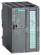
| Dimensions |
| Width |
80 mm |
| Height |
125 mm |
| Depth |
130 mm |
| Weights |
| Weight, approx. |
500 g |
| last modified: |
07/17/2018 |