| General specifications |
| Signal type | Digital Input |
| Supply |
| Connection | Power Rail or terminals 14+, 15- |
| Rated voltage | 19 ... 30 V DC |
| Ripple | ≤ 10 % |
| Rated current | 45 ... 70 mA |
| Power dissipation | 1.2 W |
| Input |
| Connection side | field side |
| Connection | terminals 1-, 2+, 3-; 4-, 5+, 6- |
| Rated values | acc. to EN 60947-5-6 (NAMUR), see system description for electrical data |
| Open circuit voltage/short-circuit current | approx. 8 V DC / approx. 8 mA |
| Switching point/switching hysteresis | 1.2 ... 2.1 mA / approx. 0.2 mA |
| Pulse/Pause ratio | min. 35 ms / min. 35 ms (non-AC operation) min. 70 ms / min. 70 ms (AC operation) |
| Line fault detection | breakage I ≤ 0.15 mA , short-circuit I > 6 mA |
| Output |
| Connection side | control side |
| Connection | output I: terminals 7, 8 ; output II: terminals 8, 9 ; output III: terminals 10, 11 ; output IV: terminals 11, 12 |
| Output I ... IV | Signal I ... Signal IV ; relay |
| Contact loading | 253 V AC/2 A /cos φ > 0.7; 40 V DC/2 A resistive load; |
| Energized/De-energized delay | approx. 30 ms / approx. 30 ms |
| Mechanical life | 5 x 10⁶ switching cycles |
| Collective error message | Power Rail |
| Transfer characteristics |
| Switching frequency | ≤ 10 Hz (non-AC operation) ≤ 3 Hz (AC operation) |
| Indicators/settings |
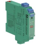
| Display elements | LEDs |
| Control elements | DIP-switch |
| Configuration | via DIP switches |
| Labeling | space for labeling at the front |
| Directive conformity |
| Electromagnetic compatibility | |
| Directive 2014/30/EU | EN 61326-1:2013 (industrial locations) |
| Low voltage | |
| Directive 2014/35/EU | EN 61010-1:2010 |
| Conformity |
| Electromagnetic compatibility | NE 21:2006 |
| Degree of protection | IEC 60529:2001 |
| Ambient conditions |
| Ambient temperature | -20 ... 60 °C (-4 ... 140 °F) |
| Mechanical specifications |
| Degree of protection | IP20 |
| Connection | screw terminals |
| Mass | approx. 150 g |
| Dimensions | 20 x 119 x 115 mm (0.8 x 4.7 x 4.5 inch) , housing type B2 |
| Mounting | on 35 mm DIN mounting rail acc. to EN 60715:2001 |
| Data for application in connection with hazardous areas |
| EU-Type Examination Certificate | ZELM 99 ATEX 0009 |
| Marking | II (1)G [Ex ia Ga] IIC
II (1)D [Ex ia Da] IIIC
I (M1) [Ex ia Ma] I |
| Fault indication output | |
| Maximum safe voltage | 40 V DC |
| Directive conformity | |
| Directive 2014/34/EU | EN 60079-0:2012+A11:2013 , EN 60079-11:2012 , EN 60079-26:2007 , EN 50303:2000 |
| International approvals |
| UL approval | |
| Control drawing | 116-0145 |
| IECEx approval | IECEx TUN 04.0003 |
| Approved for | [Ex ia Ga] IIC , [Ex ia Da] IIIC , [Ex ia Ma] I |