|
|
|
|

Image is illustrative
|
Analog Output Module CompactLogix, 8-ch. single-ended, 0/4..20mA, TS35 ^panel mount Code:
1769-OF8C
Cena (indicative)
Manufacturer
:
|
Availability:
14 days
|
Weight:
0.24 kg/pc
|
Volume:
0.0012 m3/pc
|
|
|
|
|
Controller SLC 5/05 16K Ethernet & RS-232, Allen-Bradley
1769 Compact I/O Modules
The 1769 Compact I/O modules can be used as local and distributed I/O for a CompactLogix or MicroLogix 1500 controller. Each I/O module includes a built-in removable terminal block with finger-safe cover for connections to I/O sensors and actuators. The terminal block is behind a door at the front of the module. I/O wiring can be routed from beneath the module to the I/O terminals.
When planning I/O requirements, consider:
which Compact I/O modules to use.
where to place Compact I/O modules.
how Compact I/O modules operate.

|
Certifications: (When product is marked.) C-UL certified (under CSA C22.2 No. 142), UL 508 listed, CE compliant for all applicable directives.
Digital I/O Modules
An input module responds to an input signal in the following manner:
Input filtering limits the effect of voltage transients caused by contact bounce and/or electrical noise. If not filtered, voltage transients could produce false data. All input modules use input filtering.
Optical isolation shields logic circuits from possible damage due to electrical transients.
Logic circuits process the signal.
An input LED turns on or off indicating the status of the corresponding input device.
An output module controls the output signal in the following manner:
Logic circuits determine the output status.
An output LED indicates the status of the output signal.
Optical isolation separates module logic and bus circuits from field power.
The output driver turns the corresponding output on or off.
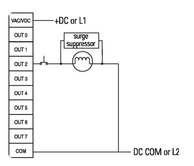
Most output modules have built-in surge suppression to reduce the effects of high-voltage transients. Use an additional suppression device if an output is being used to control inductive devices, such as relays, motor starters, solenoids, or motors. Additional suppression is especially important if your inductive device is in series with or parallel to hard contacts, such as push buttons or selector switches.
Add a suppression device directly across the coil of an inductive device to reduce the effects of voltage transients caused by interrupting the current to that device and to prolong the life of the switch contacts.

|
|
|
See product data sheet from Downloadable files.
|
|
File description
|
File type
|
Download link
|
|
|
|
|
|
Product data sheet
|
PDF
|
Download link
|
|
|
|

|
|