|
|
|
|
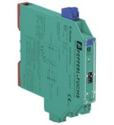
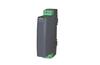
Image is illustrative
|
SMART Current Driver KCD2-SCD-Ex1, 1-ch., input 4..20mA, output 4..20mA load 650Ω, HART I/P/valve positioner, lead breakage monitoring, SIL2, 24VDC PR, Pepperl+Fuchs Code:
232717
Cena (indicative)
Manufacturer
:
|
Availability:
21 days
|
Weight:
0.105 kg/pc
|
Volume:
0.0002 m3/pc
|
|
|
|
|
SMART Current Driver KCD2-SCD-Ex1, 1-ch., input 4..20mA, output 4..20mA load 650?, HART I/P/valve positioner, lead breakage monitoring, SIL2, 24VDC PR, Pepperl+FuchsSMART Current Driver KCD2-SCD-Ex1
- 1-channel isolated barrier
- 24 V DC supply (Power Rail)
- Current output up to 650 Ω load
- HART I/P and valve positioner
- Lead breakage monitoring
- Accuracy 0.1 %
- Housing width 12.5 mm
- Up to SIL 2 acc. to IEC 61508
Datasheet excerpt: Technical data of KCD2-SCD-Ex1
| General specifications |
| Signal type | Analog output |
| Functional safety related parameters |
| Safety Integrity Level (SIL) | SIL 2 |
| Supply |
| Connection | Power Rail or terminals 9+, 10- |
| Rated voltage | 19 ... 30 V DC |
| Ripple | ≤ 10 % |
| Rated current | ≤ 30 mA |
| Power dissipation | ≤ 600 mW |
| Power consumption | ≤ 700 mW |
| Input |
| Connection side | control side |
| Connection | terminals 5-, 6+ |
| Input signal | 4 ... 20 mA limited to approx. 30 mA |
| Voltage drop | depending on switch configuration
open loop voltage of the control system < 23 V: approx. 6 V at 20 mA
open loop voltage of the control system < 27 V: approx. 10 V at 20 mA |
| Input resistance | > 100 kΩ, with field wiring open |
| Output |
| Connection side | field side |
| Connection | terminals 1+, 2- |
| Current | 4 ... 20 mA |
| Load | 0 ... 650 Ω |
| Voltage | ≥ 13 V at 20 mA |
| Ripple | 20 mV rms |
| Transfer characteristics |
| Accuracy | 0.1 % |
| Deviation | at 20 °C (68 °F), 0/4 ... 20 mA
≤ ± 0.1 % incl. non-linearity and hysteresis |
| Frequency range | field side into the control side: bandwidth with 0.5 Vpp signal 0 ... 3 kHz (-3 dB)
control side into the field side: bandwidth with 0.5 Vpp signal 0 ... 3 kHz (-3 dB) |
| Rise time | 10 to 90 % ≤ 100 ms |
| Indicators/settings |
| Display elements | LED |
| Control elements | DIP-switch |
| Configuration | via DIP switches |
| Labeling | space for labeling at the front |
| Directive conformity |
| Electromagnetic compatibility | |
| Directive 2014/30/EU | EN 61326-1:2013 (industrial locations) |
| Conformity |
| Electromagnetic compatibility | NE 21 |
| Degree of protection | IEC 60529 |
| Ambient conditions |
| Ambient temperature | -20 ... 60 °C (-4 ... 140 °F) |
| Mechanical specifications |
| Degree of protection | IP20 |
| Connection | screw terminals |
| Mass | approx. 100 g |
| Dimensions | 12.5 x 114 x 124 mm (0.5 x 4.5 x 4.9 inch) , housing type A2 |
| Mounting | on 35 mm DIN mounting rail acc. to EN 60715:2001 |
| Data for application in connection with hazardous areas |
| EU-Type Examination Certificate | CESI 06 ATEX 021 |
| Marking | II (1)G [Ex ia Ga] IIC , II (1)D [Ex ia Da] IIIC , I (M1) [Ex ia Ma] I |
| Certificate | PF 06 CERT 0973 X |
| Marking | II 3G Ex nA IIC T4 Gc |
| Directive conformity | |
| Directive 2014/34/EU | EN 60079-0:2012+A11:2013 , EN 60079-11:2012 , EN 50303:2000 |
| International approvals |
| FM approval | |
| Control drawing | 116-0419 (cFMus) |
| UL approval | |
| Control drawing | 116-0420 (cULus) |
| IECEx approval | IECEx CES 06.0001 |
| Approved for | [Ex ia Ga] IIC , [Ex ia Da] IIIC , [Ex ia Ma] I |
|
|
|

|
|