|
|
|
|
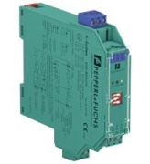
Image is illustrative
|
Switch Amplifier KFD2-SR2-Ex1.W, 1-ch., input dry contact/NAMUR, output RO, LFD, ATEX, SIL2, 24VDC PR, Pepperl+Fuchs Code:
132958
Cena (indicative)
Manufacturer
:
|
Availability:
14 days
|
Weight:
0.1575 kg/pc
|
Volume:
0.0003 m3/pc
|
|
|
|
|
Switch Amplifier KFD2-SR2-Ex1.W, 1-ch. isolated barrier, dry contact/NAMUR, relay contact output, LFD, reversible mode of operation, SIL2, 24VDC PR, Pepperl+FuchsSwitch Amplifier KFD2-SR2-Ex1.W
- 1-channel isolated barrier
- 24 V DC supply (Power Rail)
- Dry contact or NAMUR inputs
- Relay contact output
- Line fault detection (LFD)
- Reversible mode of operation
- Up to SIL 2 acc. to IEC 61508/IEC 61511
Datasheet excerpt: Technical data of KFD2-SR2-Ex1.W
| General specifications |
| Signal type | Digital Input |
| Functional safety related parameters |
| Safety Integrity Level (SIL) | SIL 2 |
| Supply |
| Connection | Power Rail or terminals 14+, 15- |
| Rated voltage | 20 ... 30 V DC |
| Ripple | ≤ 10 % |
| Rated current | ≤ 30 mA |
| Power dissipation | 0.7 W |
| Power consumption | < 0.9 W |
| Input |
| Connection side | field side |
| Connection | terminals 1+, 2+, 3- |
| Rated values | acc. to EN 60947-5-6 (NAMUR) |
| Open circuit voltage/short-circuit current | approx. 8 V DC / approx. 8 mA |
| Switching point/switching hysteresis | 1.2 ... 2.1 mA / approx. 0.2 mA |
| Line fault detection | breakage I ≤ 0.1 mA , short-circuit I > 6 mA |
| Pulse/Pause ratio | min. 20 ms / min. 20 ms |
| Output |
| Connection side | control side |
| Connection | terminals 7, 8, 9 |
| Output | signal ; relay |
| Contact loading | 253 V AC/2 A/cos φ > 0.7; 126.5 V AC/4 A/cos φ > 0.7; 40 V DC/2 A resistive load |
| Minimum switch current | 2 mA / 24 V DC |
| Energized/De-energized delay | approx. 20 ms / approx. 20 ms |
| Mechanical life | 107 switching cycles |
| Transfer characteristics |
| Switching frequency | < 10 Hz |
| Indicators/settings |
| Display elements | LEDs |
| Control elements | DIP-switch |
| Configuration | via DIP switches |
| Labeling | space for labeling at the front |
| Directive conformity |
| Electromagnetic compatibility | |
| Directive 2014/30/EU | EN 61326-1:2013 (industrial locations) |
| Low voltage | |
| Directive 2014/35/EU | EN 61010-1:2010 |
| Conformity |
| Electromagnetic compatibility | NE 21:2006 |
| Degree of protection | IEC 60529:2001 |
| Ambient conditions |
| Ambient temperature | -20 ... 60 °C (-4 ... 140 °F) |
| Mechanical specifications |
| Degree of protection | IP20 |
| Connection | screw terminals |
| Mass | approx. 150 g |
| Dimensions | 20 x 119 x 115 mm (0.8 x 4.7 x 4.5 inch) , housing type B2 |
| Mounting | on 35 mm DIN mounting rail acc. to EN 60715:2001 |
| Data for application in connection with hazardous areas |
| EU-Type Examination Certificate | PTB 00 ATEX 2080 |
| Marking | II (1)G [Ex ia Ga] IIC
II (1)D [Ex ia Da] IIIC
I (M1) [Ex ia Ma] I |
| Fault indication output | |
| Maximum safe voltage | 40 V DC (Attention! Um is no rated voltage.) |
| Certificate | PF 08 CERT 0803 |
| Marking | II (3)G [Ex ic Gc] IIC |
| Certificate | TÜV 99 ATEX 1493 X |
| Marking | II 3G Ex nA nC IIC T4 |
| Directive conformity | |
| Directive 2014/34/EU | EN 60079-0:2012+A11:2013 , EN 60079-11:2012 , EN 60079-15:2010 |
| International approvals |
| FM approval | |
| Control drawing | 116-0035 |
| CSA approval | |
| Control drawing | 116-0047 |
| IECEx approval | IECEx PTB 11.0034 |
| Approved for | [Ex ia Ga] IIC, [Ex ia Da] IIIC, [Ex ia Ma] I |
|
|
|

|
|